To study and characterize different gas sensing materials for the design of solid state gas sensors, the Electronics and Measurement Reserach Group developed a versatile measurement system housed in the Electronics, Electrical Engineering and Measurement Laboratory at the Department of Information Engineering and Mathematical Sciences, University of Siena. The system is suitable for the characterization of different kind of sensors. Recently, it has been used for conductometric metal oxide gas sensors and quartz crystal micro-balances (QCMs).
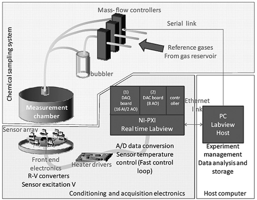
As shown in Figure 1, the measurement system is composed by three main blocks: the chemical sampling system, the conditioning and acquisition electronics and the host computer which manages the overall experiment and store data. The system is equipped with a chemical fume hood, six gas lines form a gas reservoir for the reference gases, mass-flow controllers, a bubbler, a thermostatic measurement chamber, two DAQ with several high-accuracy A/D and D/A channels, a real-time controller and a host computer. The front-end electronics changes depending on the type of sensors under test. Without loss of generality, in the following the system is decribed taking into account chemoresistive sensors.
 |
1. Introduction
Solid state gas sensors still attract the attention of many researchers, since they are the core-components of reliable on-line and low-cost gas detection systems and also of more complex equipment known as ‘artificial olfactory systems’. These latter can be of the utmost utility in many different application fields, from air-quality and process control monitoring, to food quality assessment and homeland security.
Particular attention has been devoted to the development of conductometric gas sensors based on metal oxide (MOX) sensing materials, because their low-cost production process, their large sensitivity and satisfactory stability make them the ideal candidates for the development of the above mentioned gas analysis systems.
Some semiconductor MOXs, such as SnO2 or ZnO (Barsan et al., 2007, 2011; Korotcenkov, 2007; Barsan and Weimar, 2003), have been thoroughly studied and employed in commercial structures and devices. Nevertheless, some issues related to their employment are still open (Korotcenkov and Cho, 2011) so that many research studies have proposed, even recently, some new promising material in order to overcome the problems of the most and widely studied and used MOXs. The material, when it is used to obtain chemoresistors, has a behaviour that can be hardly predicted because its overall response depends on a large number of phenomena, all of which contribute to an exchange of charge between the sensing surface and the surrounding gas, and contribute to modify the electronic conduction in the film (Fort et al., 2012). More specifically, the basis of the sensing mechanism is the adsorption of a gas in form of an ionised species [chemisorption (Wolkenstein, 1991)] that creates a charge localised on the film surface with an associate surface electric field. This latter modifies the drift of charge carriers due an external electric field. This is, in synthesis, the mechanism which causes a variation of the film conductance in response to a change in the gaseous environment. However, the magnitude and the form of this variation depend on many factors. First of all they depend on the electronic structure of the bulk material (energy band gap value, intrinsic carrier density, etc.), but they also depend on the surface structure and composition and, finally, they are strongly related to the following other aspects:
- The nature and the density of bulk and surface defects of the material, that result in free or occupied energy levels in the band gap. Even for the most studied material, that is SnO2, there are still many open issues. At this point it is important to recall that the material different characteristics have been found in materials prepared by different routes, for instance for nano-grained SnO2 with highly crystalline structure, where the bulk defect density results orders of magnitude lower than in larger grained material (Zaretskiy et al., 2012). Note, moreover, that the presence of a native population of intrinsic surface defects that can be ionised and act as charge traps, can dramatically change the behaviour of a MOX film when it is exposed to gases. In fact the grain surface can be depleted or enhanced depending on the cumulative effect of both extrinsic and intrinsic surface states. The gas sensitivity changes when comparing enhanced and depleted surfaces (Barsan and Weimar, 2003; Barsan et al., 2011; Fort et al., 2006, 2006b, 2007, 2010, 2012).
- The film microstructure, which comprises, when considering a porous film, both grain geometry and size (influencing the electric field in the grain and the potential barrier at the grain boundaries), and the type of film: poorly or well sintered. This latter aspect determines if the film conductance is mainly determined by the grain boundary Schottky barriers or by the bulk conductance (Barsan et al., 2007; Korotcenkov, 2007; Fort et al., 2012). Finally, the film thickness determines if the gas diffusion into the film has to be taken into account.
- The surface reaction of gas adsorption and charge transfer at the surface. As already stated, this is the essential sensing mechanism: the formation of localised charge on the surface caused by gas chemisorption, or the variation of free carrier density, affects the electronic conductance of the film and enables gas sensing.
All these aspects, which are crucial for the electronic conduction in sensors, are almost impossible to be a-priori known and their effect can be explored only through an experimental characterisation.
As a last remark, it must be stressed that the sensor performance is strongly dependent on working conditions in terms of temperature, humidity, and presence of interfering gases. For instance the temperature of the film usually has a dramatic influence on the sensor performance, since temperature influences both the electronic conductance and the chemical reaction kinetics and equilibria. For this reason the characterisation of the sensor should be performed in experimental conditions that grant for a very accurate knowledge of the test environment.
A further issue that makes the experimental characterisation of this kind of gas sensing materials a really hard task is their very limited response speed. For this reason very long measurements are required in order to get meaningful information in terms of reproducibility. For this reason, an experimental set-up working on an array of prototype sensors is very recommendable. In this paper a fully programmable and versatile system specifically designed for the simultaneous characterisation of up to eight novel conductometric gas sensors is presented (Addabbo et al., 2013). The system individually controls the film temperatures or measures them with an accuracy of about 1°C (at 100°C). Both chemical transients and thermal transients can be studied. These features make the system suitable for determining all the performance indexes commonly used for a gas sensing device (e.g., sensitivity, stability, selectivity, response/recovery times, etc.) as functions of various combinations of measurement conditions (e.g., gas concentrations, temperature, humidity, gas flow). Moreover, the system can perform tests based on fast temperature transients, in which the time needed to change the chemoresistor temperature is much shorter than the time constants related to chemical reaction kinetics. This test type can be useful for understanding the sensing mechanisms and for validating sensor models, as shown in the literature (Fort et al., 2006c, 2010, 2011a, 2012; Varpula et al., 2011; Ding et al., 2001).
2. System architecture
The main functions necessary for automatic characterisation of a chemosresistor that are performed by the developed system are listed below:
- Setting of a known (test) chemical environment. This is obtained by programming the gas flow, gas composition and relative humidity.
- Setting the sensing film temperature values with accuracy of few degrees Celsius (an accurate and fast setting of the temperature requires a feedback control with a fast timing).
- Acquiring the conductometric device resistance values during tests (sampling time is not an issue because the chemical responses are usually slow, with time constant form tenths of seconds to minutes).
- Processing data to derive the performance parameters.
2.1 - Sensor structure
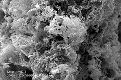
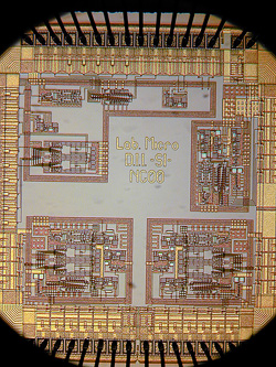
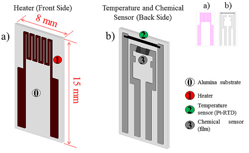
As already stated an ad-hoc structure for the development of conductometric gas sensors was designed. This structure, shown in Figure 2, allows for testing new materials prepared as micro- or nano-structured powders. On one side of a 0.2 mm thick alumina substrate an electrode pair for the chemical resistor as well as a platinum-based resistive temperature device (RTD) have been designed and built through a screen printing technique; on the other side a heater resistor has been deposited in the same way.
A sensing layer can be deposited on top of the two electrodes by screen printing, spin-, drop- or dip-coating, and subsequently dried and fired (the structure stands up to 650°C). The realisation of an RTD Pt-based sensor close to the gas sensing film allows to obtain an accurate measurement of the sensing film average temperature, which is of the utmost importance for gas sensors characterisation as already underlined in the introduction.
 |
A simulation study was performed in order to understand how the average temperature of the sensing film is related to the temperature sensed by the RTD sensor. The results it shows that in the range 150°C–400°C the difference between the sensed temperature and chemical film temperature is lower than 2°C.
2.2 - Chemical sampling system
The chemical sampling system consists of up to nine digitally-controlled mass-flow-controllers (operating in the range from 5 mL/min to 500 mL/min) that are used to set the flows of the reference gases coming from the gas cylinders. One of these is usually dedicated to a carrier gas (nitrogen or synthetic dry air), the other ones to reference mixtures of the carrier gas and target gases at known concentrations. The flows are mixed in order to obtain a mixture with selected concentrations of the target gases. The humidity level is set by a water bubbler, kept at a fixed and known temperature by a thermostatic bath, fed by the carrier gas. During the measurements the total gas flow is kept constant whereas its composition can be varied by changing the flow-meter set points. This allows to test the sensors under chemical transients or under different static chemical conditions. An important part of the chemical sampling system is the measurement chamber: the one used in the presented system is a cylindrical stainless steel chamber that can host up to eight sensors placed in a circular array. The symmetry of the chamber grants very close chemical testing conditions for all the sensors.
2.3 - Conditioning and acquisition electronics
The conditioning and acquisition electronics comprises: eight front-end boards, one board containing the heater drivers, and a real-time PXI system equipped with an eight analogue output board, a 16 single-ended analogue-input board, and a controller for real-time operations.
The eight front-end boards are mounted through connectors on a circular support-board placed in the chamber. On the front end boards, connectors tailored to the sensor pin-out allow for easy placement and substitution of the sensors. Each front-end board hosts the conditioning electronics for the measurement signals. As it can be seen in Figure 3, an R-V converter based on a constant, accurate and stable current generator and on an instrumentation amplifier is used for the read-out of the Pt-RTD value. Being this circuit very close to the sensor pins, noise and interference are minimised, and this allows for obtaining highly accurate temperature measurements.
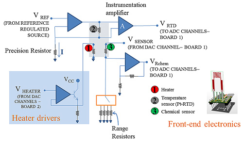 |
In particular a highly accurate current generator was designed by selecting a stable voltage generator and a precision operational amplifier. The front end board is located in the measurement chamber, where the temperature can reach approximately 50°C: this causes both the reference voltage value and the amplifier offset voltage value to drift. The effects of these non-idealities and of the finite open loop DC gain were studied, and the components were selected in order to grant a maximum error lower than 0.2°C.
The chemical sensing film resistance is converted into voltage by a voltage divider with selectable high precision reference resistances. This technique was chosen due to the large measurement range required for the sensing layer resistance which, being exponentially related to the temperature and often also to the charged adsorbed chemical species density, usually varies of some orders of magnitude during a test.
The conditioning circuits needed for heater driving are placed on a different external board, connected via a flat cable to the front-end boards.
The analogue measurement signals are fed to the 16-bit A/D converters of a commercial acquisition board (board 1 in Figure 1, National Instrument PXI-6351) hosted in a PXI rack (NI PXIe 1071). The excitation signals for the heaters are generated by a DAC board with eight analogue outputs (board 2 in Figure 1, National Instruments PXI 6713) in the same PXI rack. Finally, a controller board provides the management of the acquired data: it executes a real-time program with a 5 kHz timing, which performs sensor signal reading and a low level PID control loop for temperature management [as reported in some literature examples (Salem and Bayoumi, 2013)]. The system exploits the temperature reading from the Pt-RTDs to set the power dissipated by the sensor heaters. Being the relationship ‘dissipated power – sensor temperature’ substantially linear within the temperature range of interest, the control loop design and parameter tuning are fast and simple.
3. Film temperature measurement and control system
As described in the previous section, the control loop is implemented by the PXI real-time microcontroller, that can perform the control of eight different sensor temperatures with a 200 μs cycle time. The A/D resolution granted by the DAQ board (VLSB = 100 μV) is not an issue since it corresponds to a temperature resolution of about 0.05°C. The eight acquired VRTD voltages are real-time processed and the output voltages generated by the eight channel DAQ board are fed to the sensor heaters.
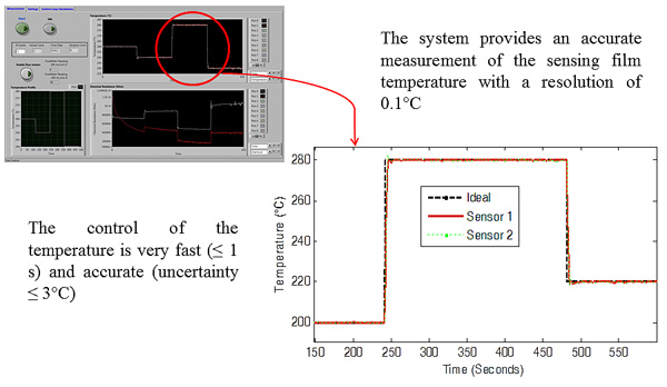 |
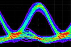
The control loop implements a PI controller designed after the characterization of the thermal system, obtaining a rise time of about 1s when avoiding the saturation of the heater voltag (see Figure 4).
4. System software
The system is completed by a software consisting of some Virtual Instruments (VIs) developed with LabVIEW. The software manages the real-time data acquisition and the above described control loop with a fast timing of 200 μs, whereas specific VIs were developed to accomplishment different type of tests. Each main VI, executed by the host, allows the setting of all the measurement parameters, included those concerning the low level PI cycle: the host at the beginning transmits them to the real-time system, in particular it uploads the desired temperature profiles, the control parameters and the parameters characterising each sensor and front-end module (gains, ranges and so on). This enables for working with different sensors and easily replacing both sensors and front-end modules.
The host starts the real-time program and controls the chemical sampling system during the measurement. Measurement data are sent to the host with a lower sampling rate, processed and displayed.
Three different main VIs were developed:
- The first VI (for ‘variable chemical condition’ tests) allows for performing tests in transient chemical conditions at fixed temperatures set by the real-time control loop. The measurements can be repeated at each temperature (in order to assess sensor stability and repeatability). This allows to study the sensor response dependence on temperature and on gas concentration; the inputs of the program, besides the parameters of the low level PI control loop, are the settings of the mass flow controllers, that corresponds to given test gas concentrations, the different temperature values used during the test, and the number of measurement repetitions for each selected temperature.
- The second VI (for ‘variable thermal condition’ tests) allows for performing tests in fixed chemical conditions but variable temperature forced by the real-time control loop. As already discussed, this kind of tests is useful for model validation. In this case the input parameters are the temperature profile (specified by a table or downloaded as a file) and the settings of the mass-flow-controllers.
- The third VI operates in open loop and allows for performing temperature measurements during chemical reactions.
All the main VIs include the possibility to start a procedure for the temperature sensor calibration. During calibration the temperature measured by the RTD-Pt screen printed sensor is compared with the one measured by a commercial PT100 device mounted on a sensor substrate heated with the same power. After the calibration procedure the estimated sensor parameters for each sensor are saved to be used in the following measurement cycles, until a new calibration procedure is executed.
References
Addabbo, T., Bertocci, F., Fort, A., Mugnaini, M., Vignoli, V., Shahin, L. and Rocchi, S. (2013) ‘Versatile measurement system for the characterization of gas sensing materials’, Proc. of IEEE I2MTC, in press.
Barsan, N. and Weimar, U. (2003) ‘Understanding the fundamental principles of metal oxide based gas sensors; the example of CO sensing with SnO2 sensors in the presence of humidity’, J. Phys.: Condens. Matter., Vol. 15, No. 20, pp.813–839.
Barsan, N., Hübner, M. and Weimar, M. (2011) Conduction mechanisms in SnO2 based polycrystalline thick film gas sensors exposed to CO and H2 in different oxygen backgrounds’, Sensors Actuators B, Vol. 157, No. 2, pp.510–517.
Barsan, N., Koziej, D. and Weimar, U. (2007) ‘Metal oxide-based gas sensor research: how to?’, Sensors Actuators B, Vol. 121, No. 1, pp.18–35.
Bicelli, S., Depari, A., Faglia, G., Flammini, A., Fort, A., Mugnaini, M., Ponzoni, A., Vignoli, V. and Rocchi, S. (2009) ‘Model and experimental characterization of dynamic behavior of low power carbon monoxide MOX sensors operated with pulsed temperature profiles’, IEEE Transaction on Instrumentation and Measurement, Vol. 58, No. 5, pp.1324–1332.
Burresi, A., Fort, A., Rocchi, S., Serrano, B., Ulivieri, N. and Vignoli, V. (2005) ‘Dynamic CO recognition in presence of interfering gases by using one MOX sensor and a selected temperature profile’, Sensors and Actuators B, Vol. 106, No. 1, pp.40–43.
Burresi, A., Fort, A., Rocchi, S., Serrano-Santos, M.B., Ulivieri, N. and Vignoli, V. (2005) ‘Temperature profile investigation of SnO2 sensors for CO detection enhancement’, IEEE Trans. on Instrumentation and Measurement, Vol. 54, No. 1, pp.79–86.
Ding, J., McAvoy, T.J., Cavicchi, R.E. and Semancik, S. (2001) ‘Surface state trapping models for SnO2-based microhotplate sensors’, Sensors Actuators B, Vol. 77, No. 3, pp.597–613.
Fort, A., Mugnaini, M., Pasquini, I., Rocchi, S. and Vignoli, V. (2011a) ‘Modeling of the influence of H2O on metal oxide sensor responses to CO’, Sensors Actuators B, Vol. 159, No. 1, pp.82–91.
Fort, A., Mugnaini, M., Rocchi, S. and Vignoli, V. (2012) ‘Surface state models for conductance response of metal oxide gas sensors during thermal transients’, in G. Korotcenkov (Ed.): Chemical Sensors: Simulation and Modeling, Vol. 2: Conductometric-Type Sensors, Momentum Press, NJ.
Fort, A., Mugnaini, M., Rocchi, S., Serrano-Santos, M.B., Spinicci, R. and Vignoli, V. (2006c) ‘Surface state model for conductance responses during thermal-modulation of SnO2-based thick film sensors: Part II: experimental verification’, IEEE Transaction on Instrumentation and Measurement, Vol. 55, No. 6, pp.2107–2117.
Fort, A., Mugnaini, M., Rocchi, S., Serrano-Santos, M.B., Vignoli, V., Atrei, A. and Spinicci, R. (2006b) ‘CO sensing with SnO2-based thick film sensors: state model for conductance responses during thermal-modulation’, Sensors Actuators B, Vol. 116, No. 1, pp.43–48.
Fort, A., Mugnaini, M., Rocchi, S., Serrano-Santos, M.B., Vignoli, V. and Spinicci, R. (2007) ‘Simplified models for SnO2 sensors during chemical and thermal transients in mixtures of inert, oxidizing and reducing gases’, Sensors Actuators B, Vol. 124, No. 1, pp.245–259.
Fort, A., Mugnaini, M., Rocchi, S., Vignoli, V., Comini, E., Faglia, G. and Ponzoni, A. (2010) ‘Metal-oxide nanowire sensors for CO detection: characterization and modeling’, Sensors and Actuators B, Vol. 148, No. 1, pp.283–291.
Fort, A., Mugnaini, M., Romualdi, L., Vignoli, V., Spinicci, R. and Rocchi, S. (2011b) ‘Development and characterization of YCoO3 based CO gas sensors’, in Proceedings of the 14th International Symposium on Olfaction and Electronic Nose, ISOEN 2011, pp.55–57, May 2–5, New York City, USA.
Fort, A., Rocchi, S., Serrano-Santos, M.B., Spinicci, R. and Vignoli, V. (2006a) ‘Surface state model for conductance responses during thermal-modulation of sno2-based thick film sensors: Part I – model derivation’, IEEE Transaction on Instrumentation and Measurement, Vol. 55, No. 6, pp.2102–2106.
Korotcenkov, G. (2007) ‘Metal oxides for solid-state gas sensors: what determines our choice?, Mater. Sci. Eng., B, Vol. 139, No. 1, pp.1–23. Korotcenkov, G. and Cho, B.K. (2011) ‘Instability of metal oxide-based conductometric gas sensors and approaches to stability improvement (short survey)’, Sensors and Actuators, B: Chemical, Vol. 156, No. 2, pp.527–538.
Salem, F. and Bayoumi, E.H.E. (2013) ‘Robust fuzzy-PID control of three-motor drive system using simulated annealing optimization’, in Journal of Electrical Engineering, Vol. 13, No. 3, pp.284–292.
Varpula, A., Novikov, S., Haarahiltunen, A. and Kuivalainen, P. (2011) ‘Transient characterization techniques for resistive metal-oxide gas sensors’, Sensors Actuators B, Vol. 159, No. 1, pp.12–26.
Wolkenstein, T. (1991) Electronic Processes on Semiconductor Surfaces during Chemisorption, Plenum Publishing Corporation, New York.
Zaretskiy, N.P., Menshikov, L.I. and Vasiliev, A.A. (2012) ‘On the origin of sensing properties of the nanostructured layers of semiconducting metal oxide